For the complete documentation index, see llms.txt. This page is also available as Markdown.

Building a 3D-HMI

Authoring the browser-based 3D-HMI in Unity with the Web* components

Overview

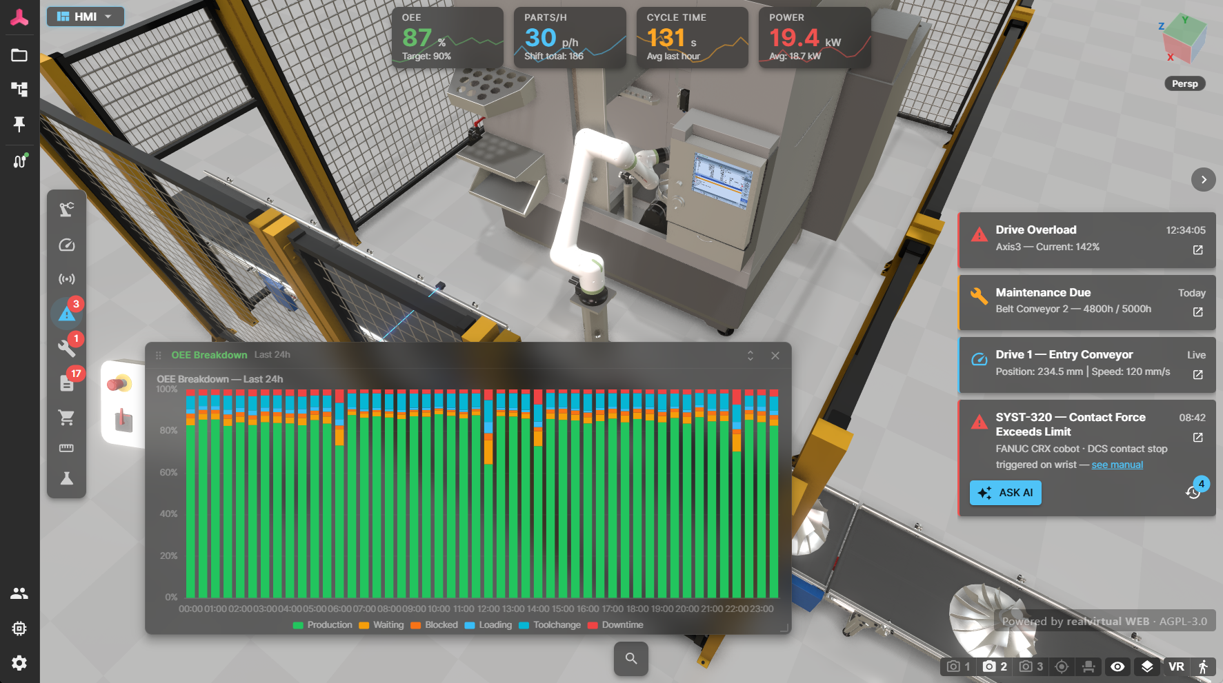
Browser-based 3D-HMI with KPI tiles, an OEE chart and a live message panel
A realvirtual WEB 3D-HMI — live KPIs, drive monitoring, message panel and document links, running in the browser
realvirtual WEB delivers the interactive 3D-HMI in the browser. You author it in Unity by adding lightweight Web* marker components to your GameObjects, binding them to PLC signals, and exporting the scene as GLB. The browser viewer reads these markers from the GLB and renders status indicators, error highlights, safety-zone overlays, operator instructions and digital-twin links — connected to live signals.

These components replace the deprecated Unity uGUI HMI components. Instead of building a 2D operator panel inside the Unity scene, you annotate the 3D model itself, and the HMI runs in any browser.

Most Web* components are pure markers — they have no Unity runtime function and only describe how a node is visualized in realvirtual WEB. Add them, bind a signal, set a label, and export.

From Virtual Commissioning to 3D-HMI

A realvirtual 3D-HMI is not built from scratch — it is the delivery form of the model you already built for simulation and virtual commissioning. In the typical engineering workflow the behavior model comes first, and the HMI is the last step:

  1. Engineering / virtual commissioning — import the CAD, add drives, sensors, kinematics and signals, and test the control logic against the physics-based model with a virtual or real PLC, before the machine is built.

  2. Delivery / 3D-HMI — add the Web* markers below to the finished model, export it as GLB, and deliver it to any browser as a live operator HMI connected to the running machine.

The same drives, sensors, signals and kinematics that drive the simulation drive the HMI. You reuse the validated commissioning model rather than rebuilding it — the 3D-HMI is a natural continuation of the engineering work, not a separate project.

Quick Start

  1. Select the GameObject you want to annotate (a machine part, a sensor, a door).

  2. Add a Web* component from the realvirtual → WebHMI component menu (for example Web Sensor).

  3. Bind the relevant PLC signal(s) and set a label or text.

  4. Export the scene with Tools → realvirtual → Export → WebViewer Tools and open it in the browser.

Showing Machine Motion

The core of a 3D-HMI is the machine moving as it really does. realvirtual drives animate the model directly from live PLC signals, so the browser shows the true machine state — there is no separate animation to maintain, and the same drives you use for virtual commissioning drive the HMI.

Component
HMI use

Drive

Moves an axis (linear or rotational) to visualize live position or motion.

Drive_FollowPosition

Mirrors a real axis 1:1 — the drive follows a PLC position signal (for example an encoder value) directly, with scale and offset. The best choice for reflecting the actual machine position in the HMI.

Drive_Cylinder

Shows a pneumatic actuator moving between its two end positions from a bool signal, with end-position feedback — ideal for cylinders, clamps and stoppers.

Drive_Speed

Moves or rotates a component at a live commanded speed, for example a conveyor.

See drive behaviors for the full list. Combine motion with the markers below: the drive shows what the machine is doing, while WebSensor and WebError overlay its status.

Web Sensor

Component menu: realvirtual → WebHMI → Web Sensor

Visualizes a signal as a color-coded 3D status indicator with four states — Low, High, Warning, Error — using ISA-101 aligned colors (grey / blue / amber / red, with amber blinking at 1 Hz and red at 2 Hz). Bind either a bool signal (2 states) or an int signal (4+ states).

Property
Description

Signal Bool (PLCOutputBool)

Binary input: false = Low, true = High. Use for two-state indicators.

Signal Int (PLCOutputInt)

Integer input mapped to a state through the Int State Map. Wins if both signals are set.

Int State Map (string)

Maps integer values to states. Empty = default (0=Low, 1=High, 2=Warning, 3=Error). Format: comma-separated value:state pairs, e.g. 0:low,1:high,5:warning,99:error. Unlisted values map to Low.

Label (string)

Optional label shown in the tooltip and the sensor list.

Web Error

Component menu: realvirtual → WebHMI → Web Error

Marks a part as an error source. While the signal is high, the part is highlighted, the error text appears as a badge next to it, and the error is listed as a card in the message panel (clicking it focuses the part). Can also be used without a signal as a static hint.

Property
Description

Signal Error (PLCOutputBool)

true = error active, false = OK. Leave empty for a static hint marker.

Error Text (string)

Human-readable error message shown as a 3D badge and in the message panel.

Highlight Style (Auto / Flash Object / Circle)

How the part is highlighted. Auto lets the viewer choose by part size; Flash Object glows the mesh red at 2 Hz; Circle draws a red floor ring.

Web Visibility

Component menu: realvirtual → WebHMI → Web Visibility

Shows or hides parts from a signal, with an optional error state. Unlike the other markers this component also works inside Unity at runtime.

Property
Description

Signal Visible (PLCOutputBool)

true = visible, false = hidden. Empty = use Default Visible.

Invert Signal (boolean)

Inverts the visibility logic (signal false = visible).

Default Visible (boolean)

Visibility used when no visibility signal is bound.

Additional Targets (list)

Extra GameObjects shown / hidden together with this object.

Signal Error (PLCOutputBool)

true = error active (red, flashing). Empty = no error state.

Error Text (string)

Error message shown as a 3D badge and in the message panel.

Highlight Style (Auto / Flash Object / Circle)

How the faulty part is highlighted.

Error Color (color)

Color of the error highlight (Unity overlay and WEB).

Blink Speed (float)

Blink speed of the error highlight. Higher = faster.

Web Safety Door

Component menu: realvirtual → WebViewer → Web Safety Door

Adds a safety-door overlay: an amber outline around the door mesh, a translucent hazard-zone halo on the floor, and a billboard label. Overlay only — the door mesh is never recolored.

Property
Description

Hazard Zone Radius (float, mm)

Radius of the floor halo that visualizes the hazard zone below the door.

Label Height (float, mm)

Height of the billboard label above the floor. Sits low by default so it does not occlude the door.

Custom Runtime Instruction

Signal-activated operator instruction shown in the message panel. Supports a single message or an ordered list of steps; each step can highlight and frame target objects in the 3D scene and link a document.

Property
Description

Type (Info / Maintenance / Warning / Error / Success)

Determines the title, icon and border color.

Dismissible (boolean)

If true, the operator can acknowledge the message; it reappears on the next rising signal edge. If false it stays while the signal is high.

Isolate (boolean)

realvirtual WEB only: clicking the message isolates the step's targets (dims the rest of the scene) in addition to camera focus and highlight.

Signal (PLCOutputBool)

Optional. Rising edge pushes the message, falling edge dismisses it.

Steps (list)

Ordered instruction steps. Each step has instruction text, target objects (highlighted in parallel and framed), and an optional document URL.

Component menu: realvirtual → AAS → AAS Link

Links a part to an Asset Administration Shell. In the browser the AAS identifier is resolved against a local AASX index (or fetched from a server URL) and the Nameplate and Technical Data are shown as a tooltip on hover or selection.

Property
Description

AAS Id (string)

AAS identifier, e.g. http://smart.festo.com/aas/99920200623113326000013225.

Description (string)

Optional description shown in the tooltip header.

Server Url (string)

Optional AAS server URL. Empty = load the AASX from the local aasx/ folder.

Web Pivot

Component menu: realvirtual → WebHMI → Web Pivot

Defines the explicit pivot point of a library object for realvirtual WEB. Place it on an empty child GameObject; the child's transform position becomes the pivot the viewer uses for gizmos, layout snapping and rotation, instead of the default auto pivot (bottom-center of the bounding box). Use exactly one per library object. This component has no properties — only its position matters.

Tooltips and Metadata

RuntimeMetadata carries per-part information such as article numbers and descriptions. In realvirtual WEB it drives hover tooltips and is the key that links a part to its documentation.

Attaching Documents

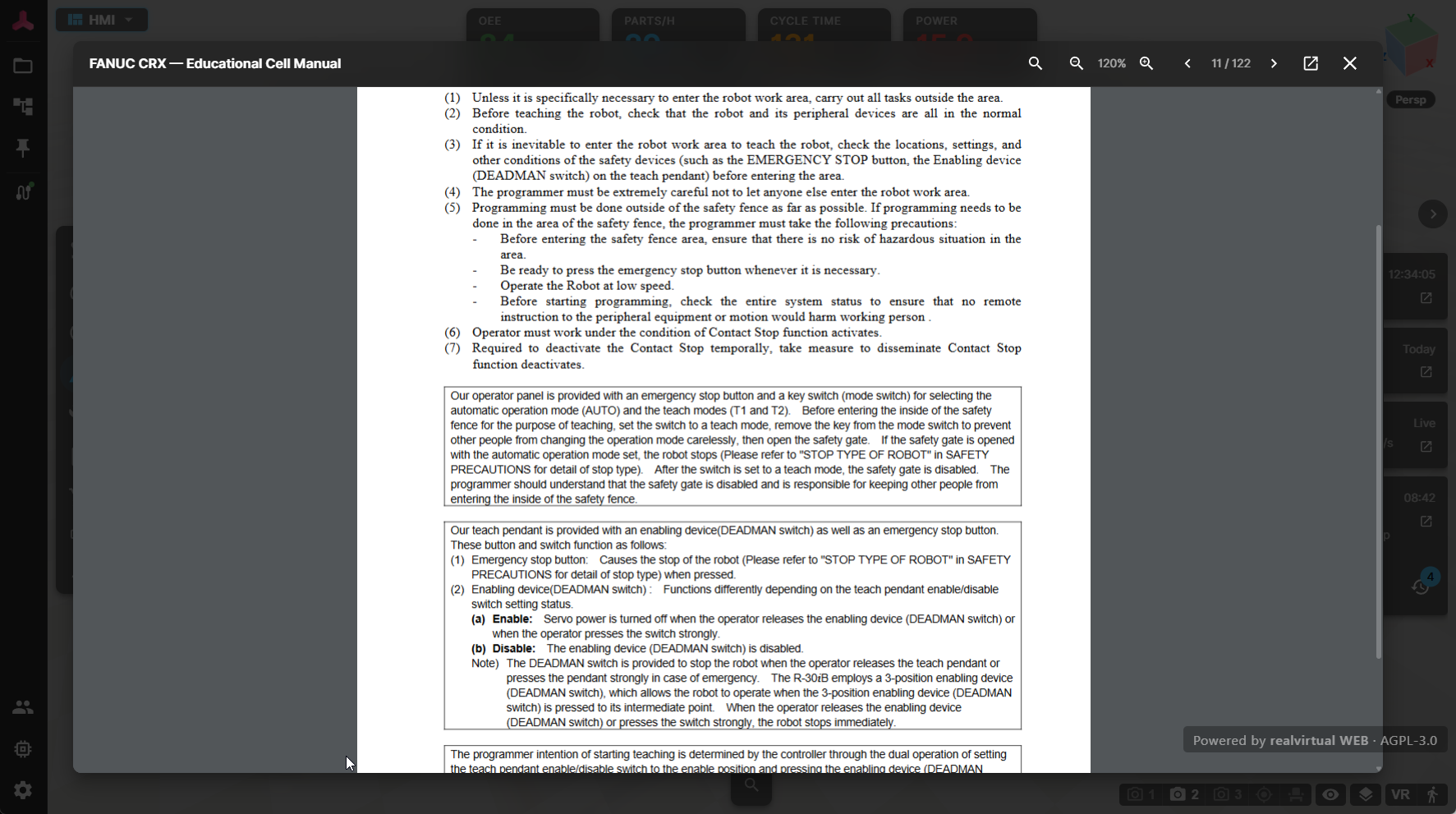
You can attach documentation — data sheets, maintenance instructions, spare-part lists — directly to the parts of the 3D model. The link is made by article number: each part carries its article number in RuntimeMetadata, and a document index maps article numbers to PDF files. In the browser, parts that have documentation are highlighted, a document button opens the PDF browser, and hovering a part reveals its document link.

This is how production 3D-HMIs use it in practice: every CAD part carries its article number, and the operator opens the matching data sheet or maintenance PDF straight from the 3D model.

A machine manual PDF opened inside the browser 3D-HMI, deep-linked from an alarm
The machine manual opens directly inside the 3D-HMI, deep-linked to the relevant page
Documents are served alongside the deployment — no document content is embedded in the GLB. The GLB only carries the article numbers via RuntimeMetadata.

Outlook — AI-Assisted Diagnosis

Attaching documents also opens the door to AI-assisted operation. When the attached PDFs are indexed in a vector database, a large language model can answer questions and diagnose faults against your own documentation:

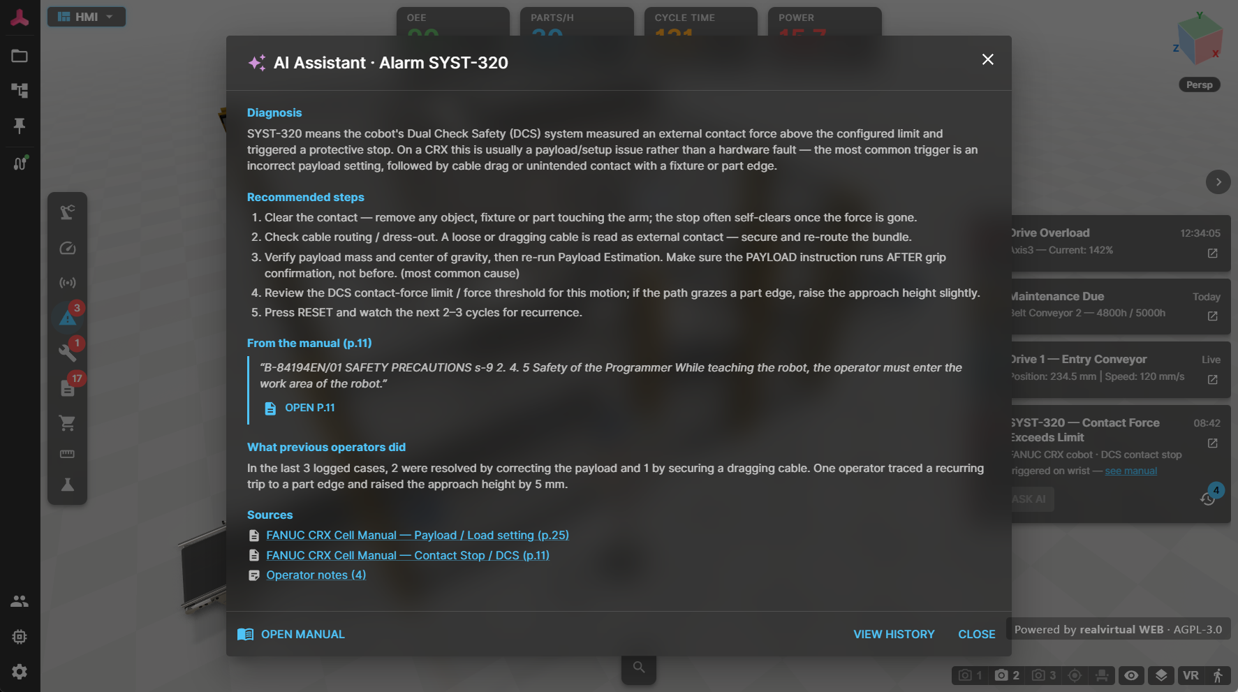
AI assistant panel diagnosing an alarm with cause, recommended steps and cited manual sources
AI-assisted diagnosis of an alarm — cause, recommended steps and cited sources with page-level deep links into the manuals
  • WebDiagnostics couples a PLC error signal to an AI diagnosis. On a fault it returns the likely cause, a suggested remedy, and the exact PDF sources — with page-level deep links into your manuals.

  • The AI runs server-side through realvirtual CONNECT: the LLM keys, the vector index and the PDF full text stay on the server, and the browser only sends the request and shows the result.

This turns the 3D-HMI from a monitoring view into an assistance system grounded in the machine's real documentation.

See Also

Last updated