> For the complete documentation index, see [llms.txt](https://doc.realvirtual.io/llms.txt). Markdown versions of documentation pages are available by appending `.md` to page URLs; this page is available as [Markdown](https://doc.realvirtual.io/components-and-scripts/motion/kinematic-joints.md).

# Kinematic Joints (Pro)

{% hint style="info" %}
This feature was added in realvirtual **6.3.x** (Professional).
{% endhint %}

## Overview

Kinematic Joints add a purely kinematic, position-based constraint solver to realvirtual. They solve **closed kinematic chains** — Delta robots, four-bar linkages, scissor lifts, parallel grippers — without using Unity's physics engine at all. A `KinematicMechanism` collects every `KinematicJoint` in its hierarchy and, once per FixedUpdate, moves every passive link so that all joint constraints are satisfied, given the current position of your `Drive` components. There is no jitter, no drift, and no PhysX involved: the same Drive input always produces the exact same result.

This is a different, fourth path alongside realvirtual's existing motion systems (kinematic hierarchy Drives, `Joint`/PhysX joints, `Kinematic`/CAD pivot correction — see [Joint](/components-and-scripts/motion/joint.md) and [Kinematic](/components-and-scripts/motion/kinematic.md)). Use Kinematic Joints specifically when a mechanism cannot be expressed as a simple parent/child hierarchy because one link has to satisfy more than one constraint at the same time — the defining trait of a closed loop.

{% hint style="success" %}
**Accuracy, not physics.** A PhysX `Joint` solves a closed loop with iterative, force-driven physics, so it tends to jitter, sag and drift, needs spring/damper tuning to stay stable, and is not exactly repeatable. Kinematic Joints satisfy the geometry *exactly* every FixedUpdate — no jitter, no drift, fully deterministic. Whenever the mechanism's pose has to be *correct* (a Delta picking to a precise point, a linkage indexing to a fixed stop, a gripper closing to an exact width), use Kinematic Joints; reach for a physics joint only when the dynamics themselves are what you want to simulate.
{% endhint %}

Drives keep working exactly as you already know them. A Drive still owns its own axis and moves it with speed, acceleration and limits. The only difference is that a `KinematicJoint` references that Drive as its **Driven By** field — the joint becomes the active boundary condition the solver treats as fixed for that step, and everything downstream (the passive links) is calculated from it.

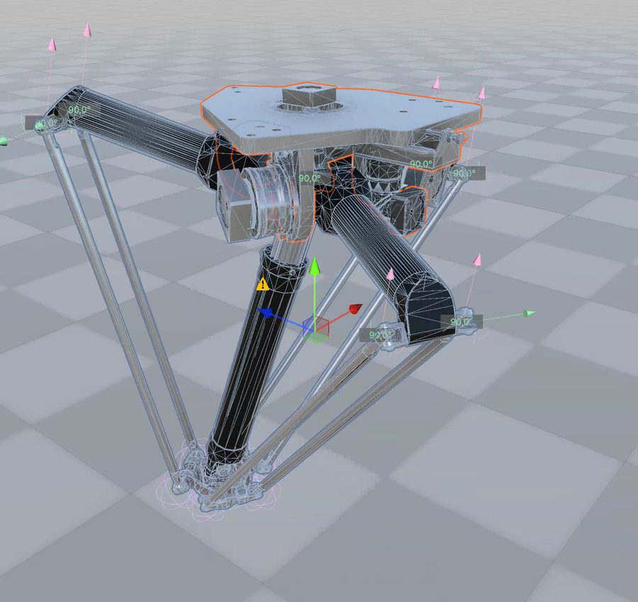
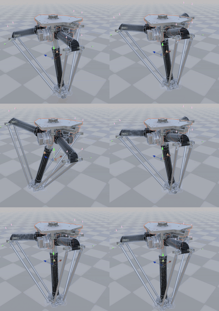
<figure><img src="/files/beKlABk9UO4fVxDudEgw" alt=""><figcaption><p>A real Autonox delta robot (CAD import) running purely on Kinematic Joints: three driven arms close a Universal–Spherical parallelogram onto the floating platform, plus a telescope axis and a driven TCP rotation. This is the <strong>DemoKinematicsSolver</strong> sample scene (menu <strong>realvirtual/Kinematics</strong> demos).</p></figcaption></figure>

{% hint style="info" %}
The Autonox robot in the demo scene was reconstructed from the manufacturer's public connecting-dimensions drawing, not from exact internal CAD. The joint positions are plausible and the mechanism solves cleanly, but the arm/rod geometry is approximate — treat the demo as a showcase of the solver, not as a dimensionally accurate Autonox model.
{% endhint %}

## Key Concepts

**Floating links.** Links that form part of a closed loop do not need to be parented to each other. A coupler link in a four-bar linkage, for example, sits directly under the mechanism root and is positioned purely by its `KinematicJoint` connections — this is what makes closed loops possible in the first place.

**Four joint types.** Revolute (hinge), Prismatic (slider), Spherical (ball joint) and Universal (cardan) cover the vast majority of mechanical joints. A Universal joint is required wherever a rod would otherwise be held only by two Spherical joints — that configuration has a free spin degree of freedom around the rod's own axis, which realvirtual detects and flags with a console warning.

**Active vs. passive joints.** A joint becomes "active" the moment you assign a Drive to its **Driven By** field. Active joints are the boundary conditions of the solve; every other joint is passive and gets its value calculated by the solver every FixedUpdate.

**Diagnosis, not silent failure.** If a mechanism is pushed to or beyond a joint limit, or into a configuration it cannot exactly reach, the solver converges to the closest achievable pose instead of tearing the chain apart. `Converged` and `Residual Error` on the `KinematicMechanism` make this visible at a glance, and an optional `Signal Converged` PLC signal exposes it to your automation logic.

## Joint Types

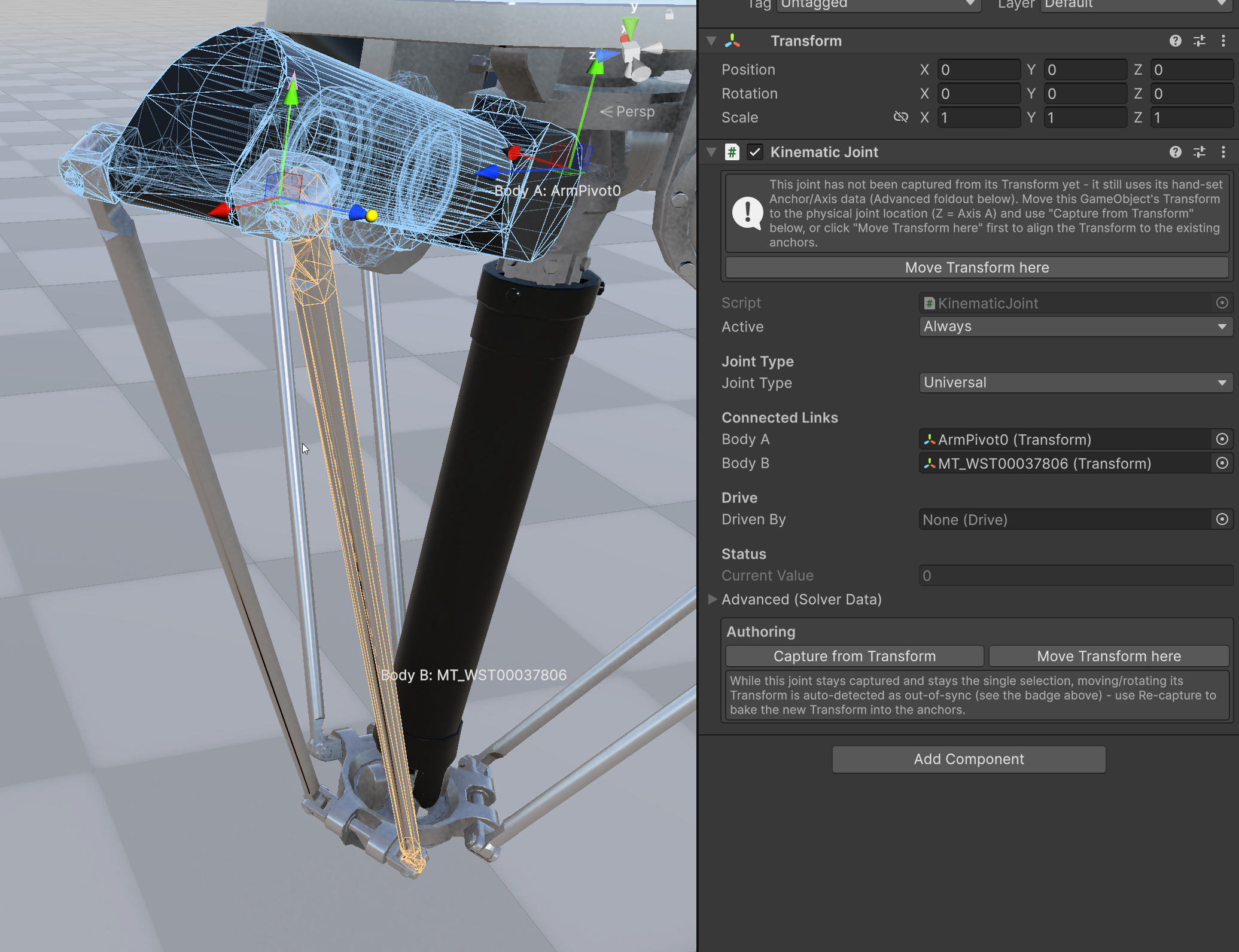
Every `KinematicJoint` is one of four types. The type decides how many degrees of freedom the joint leaves open, which anchor/axis fields you need to fill in, and how the joint is drawn in the Scene View. When you select a joint (or its `KinematicMechanism`), each joint draws a type-specific, color-coded gizmo; selecting a single joint additionally highlights its two connected links as a wireframe — **Body A in blue, Body B in orange** — so you can see at a glance which two parts a joint ties together.

<figure><img src="/files/Ffp6TUbcQCqCauXdS290" alt=""><figcaption><p>Scene View joint gizmos on the Autonox delta: the green/pink Cardan crosses are Universal joints, each with a live 90° angle label between its two axes; the orange outline marks the selected link.</p></figcaption></figure>

**Revolute — 1 rotational DOF (hinge).** Rotates about a single axis. Fill in **Anchor A** (the hinge point) and **Axis A** (the rotation axis, in Body A's local space). This is the only joint type besides Prismatic that carries a single scalar value, so it is the type you normally make *active* by assigning a **Driven By** Drive, and the only type (with Prismatic) that supports **Use Limits**. Gizmo: a blue disc in the rotation plane with an axis arrow, plus a green limit arc that turns red as the joint approaches a limit. Typical use: robot arm axes, four-bar cranks and rockers, the driven arms of a Delta robot.

**Prismatic — 1 translational DOF (slider).** Slides along a single axis. Anchor A and Axis A define the slide line; **Use Limits** clamps the travel in millimeters. Gizmo: an orange slide line with end markers and a cube marker at the current position. Typical use: scissor-lift strokes, linear actuators, the telescope axis of the Autonox demo.

**Spherical — 3 rotational DOF (ball joint).** A free ball joint with no single axis — only **Anchor A** and **Anchor B** matter, Axis A and limits are hidden. Gizmo: three orthogonal wireframe rings (a wire sphere) at the anchor. Typical use: the lower end of parallelogram rods, ball-jointed linkages. A rod held by *two* Spherical joints has a free idle-spin degree of freedom around its own axis, which the solver flags as a warning — use a Universal joint at one end instead (see below).

**Universal — 2 rotational DOF (Cardan / U-joint).** Transmits rotation while allowing a bend, like a cardan/universal joint. It needs **two** axes: **Axis A** in Body A's space and **Secondary Axis B** in Body B's space, which should be perpendicular at the assembled pose. Gizmo: a stylized Cardan cross (two perpendicular yoke forks) with a live angle label — green at 90°, orange as the two axes drift away from square. This is the required upper-joint type of a Delta parallelogram: pairing one Universal with one Spherical per rod removes the idle-spin freedom that two Spherical joints would leave.

<figure><img src="/files/LvPjx2lmyuI2uGo75G7y" alt=""><figcaption><p>A Universal joint of the delta parallelogram selected: the Inspector shows Body A (ArmPivot0) and Body B (rod), the connected-link wireframe highlight (blue = Body A, orange = Body B), and the Transform-authoring section.</p></figcaption></figure>

## Properties

### KinematicJoint

**Joint Type** (enum) Selects the constraint: Revolute (1 rotational DOF), Prismatic (1 translational DOF), Spherical (3 rotational DOF, no single axis) or Universal (2 rotational DOF, cardan-style).

**Body A** / **Body B** (Transform) The two links this joint connects. Body A may be left empty to anchor the joint against world/static space; Body B is always required.

**Anchor A** / **Anchor B** (Vector3, millimeters) The joint's pivot point, given in each body's own local space.

**Axis A** (Vector3) The joint axis in Body A's local space. Used by Revolute, Prismatic and Universal; not shown for Spherical, which has no single axis.

**Secondary Axis B** (Vector3) The second joint axis, in Body B's local space — Universal joints only.

**Use Limits** (boolean) Clamps the joint's value between Lower Limit and Upper Limit. Available for Revolute and Prismatic joints, which have a single scalar value a limit can clamp.

**Lower Limit** / **Upper Limit** (float) The clamping range, in degrees (Revolute) or millimeters (Prismatic).

**Driven By** (Drive) The Drive that actively controls this joint. Leave empty for a passive joint the solver calculates.

**Current Value** (float, read-only) The joint's current value in degrees or millimeters, written by the solver every FixedUpdate for diagnosis.

### KinematicMechanism

**Solver Iterations** (int) The fixed number of Newton-Raphson iterations run every FixedUpdate. Four is enough for most mechanisms; a Delta robot with several floating links benefits from a higher value (the demo scene uses twelve).

**Damping** (float) The damped-least-squares factor that keeps the solver stable near singular configurations. The default works well for typical mechanisms.

**Tolerance** (float, millimeters) The residual error below which the mechanism reports `Converged = true`.

**Converged** (boolean, read-only) Whether the last solve met Tolerance.

**Residual Error** (float, read-only) The largest remaining constraint error of the last solve, in millimeters — visible directly in the Inspector's Diagnosis panel with a green check or red cross.

**Signal Converged** (PLCOutputBool) Optional PLC signal mirroring Converged, so your control logic can react to a mechanism that has run into a limit.

## Quick Start

1. Create an empty GameObject for your mechanism and add a **Kinematic Mechanism** component (`realvirtual/Kinematics/Kinematic Mechanism`).
2. Add the links as children — the fixed frame, any Drive-controlled links, and any floating (loop) links.
3. Add one **Kinematic Joint** component (`realvirtual/Kinematics/Kinematic Joint`) per connection between two links, and set Body A, Body B, Anchor A/B and Axis A.
4. For every joint a Drive should control, assign that Drive to **Driven By**.
5. Press **Validate Mechanism** in the `KinematicMechanism` Inspector to check the topology (link/joint count, independent loops, an estimated degree-of-freedom count) before pressing Play.
6. In Edit Mode, use **Solve Now** to preview a single solve pass without entering Play Mode — the change is fully undoable.
7. Enter Play Mode and drive your Drives as usual. The mechanism solves automatically every FixedUpdate.

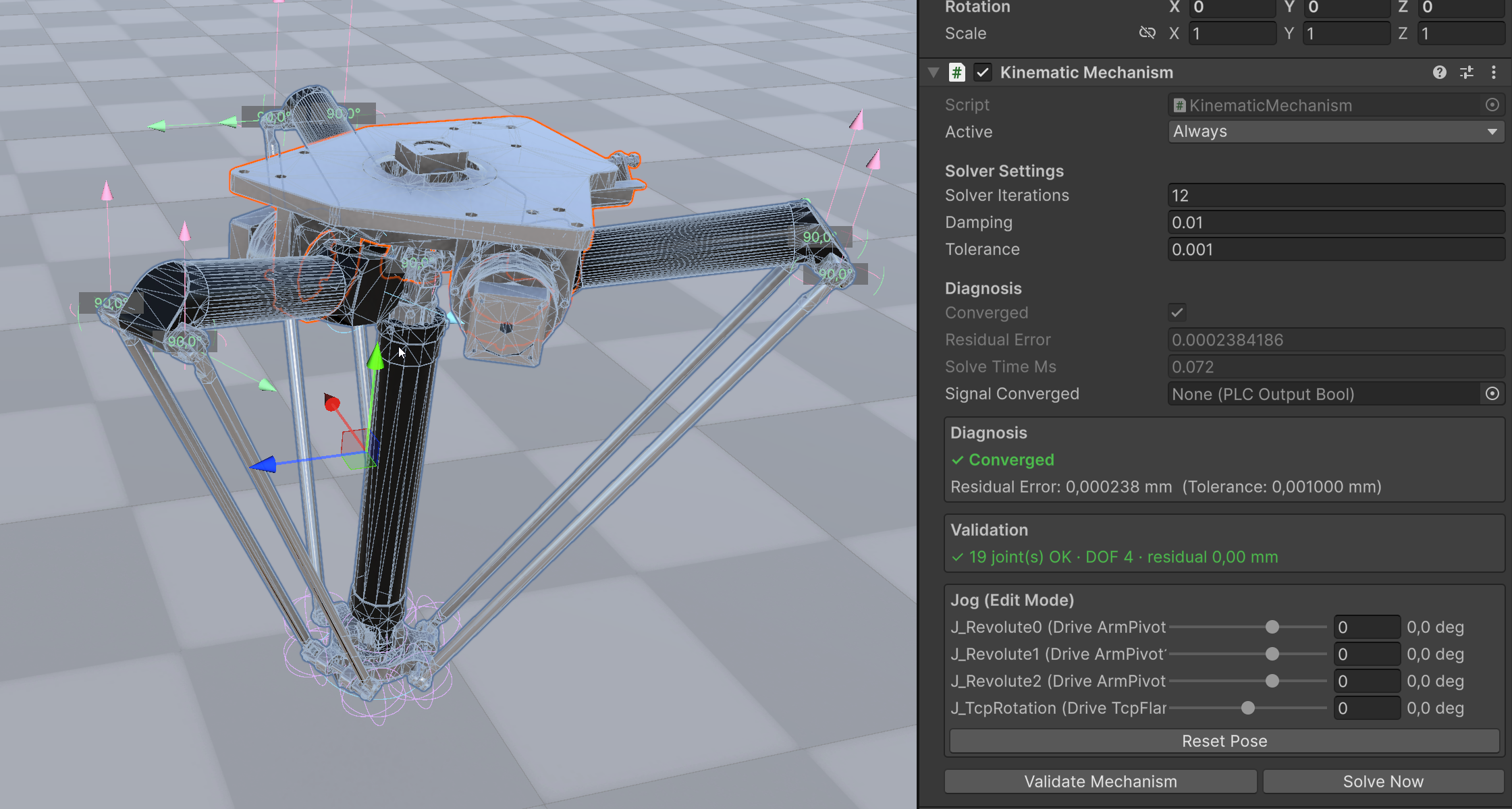
<figure><img src="/files/GMtnoSW4nXU57NzxnMBy" alt=""><figcaption><p>The KinematicMechanism Inspector: live Diagnosis (Converged, Residual Error, Solve Time), the Validation panel (here <em>19 joints OK · DOF 4</em>), and per-joint Edit-Mode Jog sliders that drive the mechanism without entering Play Mode.</p></figcaption></figure>

## Editor Tools

Anchor A and Axis A can be dragged directly in the Scene View when a `KinematicJoint` is selected — a position handle for the anchor and a free-move handle for the axis direction. Gizmos color-code every joint by type (blue disc for Revolute, orange for Prismatic, purple sphere for Spherical, two colored arrows for Universal) and show a limit arc that turns red once a Revolute or Prismatic joint approaches its limit. Selecting the `KinematicMechanism` additionally draws a connector line between every joint's Body A/B anchors — this line turns into a dashed yellow warning line if the mechanism's residual error exceeds Tolerance, making an unreachable configuration visible at a glance.

The **Kinematic Joint** section in the [Kinematic Tool](/basics/user-interface/kinematic-tool-pro.md) window reuses the tool's existing pivot/bounding-box axis definition to quickly place joint anchors on CAD meshes.

## Inverse Mode / Kinematic Target

{% hint style="info" %}
This feature was added in realvirtual **6.3.x** (Professional).
{% endhint %}

Everything above describes the **forward** direction: Drives in, passive link poses out. `KinematicTarget` adds the reverse direction to the same solver — a Cartesian world-space position in, driven-joint values out. Attach it to any GameObject, set **Mechanism** and **Target Link** (the mechanism's own link that should follow this GameObject, e.g. a Delta robot's platform), and enable **Tracking Active**: every FixedUpdate the mechanism's Drives are solved so Target Link converges towards the GameObject's own position. This is the generic replacement for a per-mechanism analytical inverse kinematics implementation — any mechanism this system can already solve forward, it can now also solve inverse, using the same damped-least-squares approach and the same "closest achievable pose" behavior for unreachable targets.

Position only — there is deliberately no orientation target. The parallel-kinematic platforms this system targets (Delta robots above all) have no independent orientation degree of freedom at all; their platform orientation is a byproduct of the parallelogram-arm geometry, not a controllable input, so an orientation constraint would simply over-constrain a solve that position alone already fully determines.

**Mechanism** (KinematicMechanism) The mechanism whose actively-driven joints are solved for this target.

**Target Link** (Transform) The mechanism's own link that should track this GameObject's world position — typically the same link a forward-mode setup would read for diagnosis (a Delta robot's platform, a scissor lift's top stage).

**Tracking Active** (boolean) Enables continuous inverse-mode tracking. While active, the driven Drives are released from their normal Jog/Drive To/speed-ramp behavior (`Drive.IsExternallyControlled`) so this component's writes are authoritative — the same convention `RobotIK` uses for its own IK solutions. Disabling it hands the Drives back to their usual behavior.

**Reachable** (boolean, read-only) Whether the last inverse solve converged exactly on the target position. `false` means the target sits outside the mechanism's workspace or a Drive limit was hit — the mechanism still moves to the closest achievable pose instead of freezing, exactly like the forward solver's own diagnosis.

A small crosshair marks the target position in the Scene View, with a dotted line to Target Link's current position — green while reachable, red when the target is outside the workspace.

For scripted or programmatic use without a live-tracking GameObject, `KinematicMechanism` exposes the underlying solve directly:

```csharp
// Pure calculation, does not move the scene:
float[] jointValues = new float[mechanism.GetActiveJointCount()];
bool reachable = mechanism.SolveInverse(targetWorldPosition, platformLink, jointValues);

// Solves AND writes the result into the driven Drives:
bool reachable = mechanism.DriveToPosition(targetWorldPosition, platformLink);
```

## Performance

The constraint solver runs in a high-performance **native core**, not in managed script code. Even a demanding closed-loop mechanism like the Autonox delta — 19 joints, ten floating bodies, roughly 66 generalized coordinates — solves in well under a tenth of a millisecond per FixedUpdate. The live **Solve Time Ms** field on the `KinematicMechanism` Diagnosis panel shows this directly (about 0.07 ms for the Autonox demo).

Mechanisms are also solved **in parallel**. When a scene contains many independent mechanisms, realvirtual gathers them into one batch each FixedUpdate and solves them across worker threads, then writes every result back on the main thread in a deterministic order. In a stress-test scene of **100 full Autonox delta robots** (1900 joints in total) the entire batch solves in roughly **8 ms per FixedUpdate** — comfortably real-time — where a naive one-after-another approach would need hundreds of milliseconds. The result stays fully deterministic: identical Drive inputs always produce identical poses, whether one mechanism runs or a hundred.

You never configure any of this. Build your mechanism, press Play, and the solver picks the fast path automatically.

## Common Use Cases

**Delta robots** – Three Drive-controlled arms, each closing a Universal-Spherical parallelogram onto a floating platform. This is the reference mechanism the solver was validated against — the platform stays purely translational (no rotation) as the arms move, exactly like a physical Delta robot.

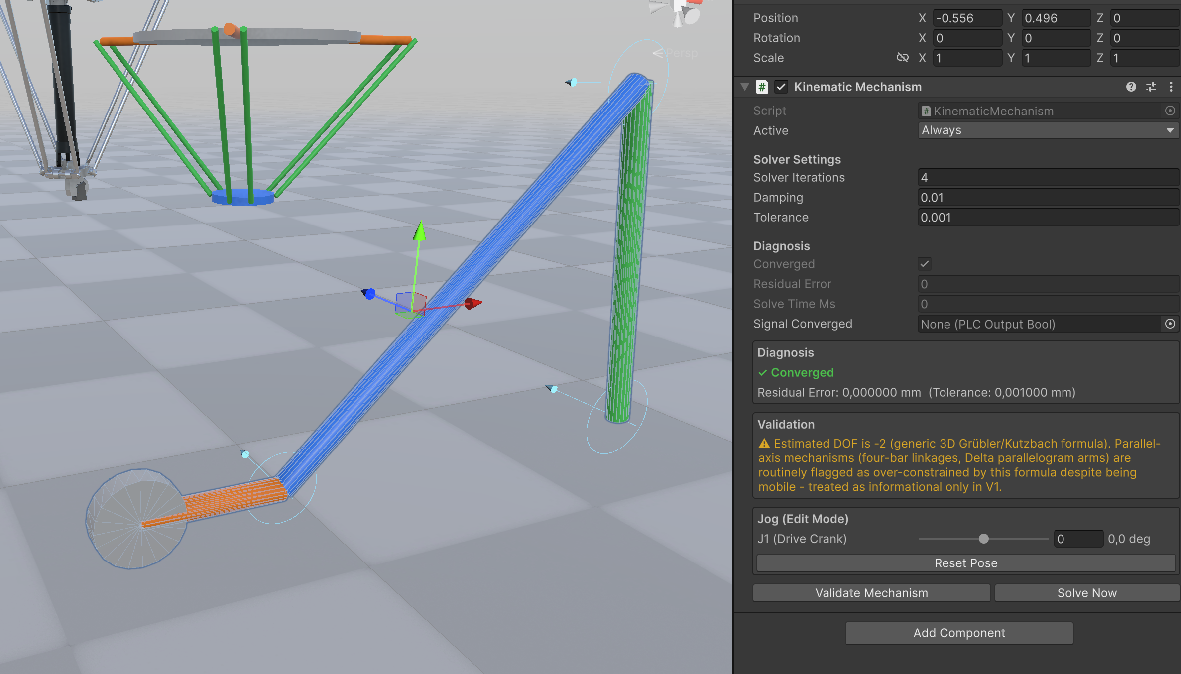
<figure><img src="/files/zdQ0pmXjiOYu6IvV5iFI" alt=""><figcaption><p>The primitive four-bar linkage and Delta robot from the demo scene. The four-bar's Validation panel shows the expected <em>DOF −2</em> note: the generic Grübler/Kutzbach formula routinely flags parallel-axis mechanisms as over-constrained even though they move freely — informational only.</p></figcaption></figure>

**Scissor lifts** – A single Drive-controlled Prismatic joint pushes the base of a scissor stage; the platform height follows automatically from the geometry.

**Four-bar / coupler linkages** – A Drive-controlled crank moves a coupler and rocker link through a closed loop, useful for cams, indexing mechanisms and toggle clamps.

**Parallel grippers** – Two or more jaws that must open/close symmetrically from a single Drive, connected through a shared coupler link.

## Limitations (V1)

**Joint types.** The four types cover the vast majority of industrial mechanisms, but three multibody joint types are not yet built in:

* **Cylindrical** — rotation *and* translation about the *same* axis at once (2 DOF), as in a rotating telescopic shaft. Model it today as a **Revolute + Prismatic** pair on a shared intermediate link (one dummy link between the two joints, both using the same axis). The Autonox demo's telescope is built this way.
* **Planar** — two translations plus one rotation in a plane (3 DOF).
* **Screw / helical** — rotation and translation rigidly coupled by a lead (a threaded spindle). A separate `Drive` gear/ratio coupling is the current workaround.

There is deliberately no fixed/weld joint — two links that never move relative to each other are simply parented in the hierarchy.

**Other V1 limits.**

* Kinematic Joints solve only in **Play Mode**, because the solve runs on Unity's `FixedUpdate` step, which Unity itself only executes while playing. Use **Solve Now** (or the Jog sliders) in the `KinematicMechanism` Inspector for a fully-undoable Edit Mode preview.
* **Nested mechanisms** (a `KinematicMechanism` inside another one) are not supported and are flagged as a configuration error — each mechanism is solved as one self-contained constraint graph.
* A mechanism has **one grounding reference** (its fixed frame, or world). Any number of joints may anchor to that same ground — a four-bar linkage's two ground pivots, for example, both anchor to the frame link. What is not supported is *two independent* static bases in a single mechanism (flagged as a configuration error); model the two pivots against a shared frame link, or split them into separate mechanisms.
* The solver runs in a native core; the **Windows** Editor and Standalone player are supported out of the box.

## See Also

* [Drive](/components-and-scripts/motion/drive.md) — the active axis every driven Kinematic Joint references
* [Joint](/components-and-scripts/motion/joint.md) — the PhysX-based alternative for backward kinematics
* [Kinematic](/components-and-scripts/motion/kinematic.md) — CAD hierarchy/pivot correction (unrelated despite the similar name)
* [Kinematic Tool](/basics/user-interface/kinematic-tool-pro.md) — editor workflow for building mechanisms on CAD meshes

\
© 2026 realvirtual GmbH [https://realvirtual.io](https://realvirtual.io/) - All rights reserved. No part of this publication may be reproduced, distributed, or transmitted in any form or by any means, including printing, saving, photocopying, recording, or other electronic or mechanical methods, without the prior written permission of the publisher.


---

# Agent Instructions
This documentation is published with GitBook. GitBook is the documentation platform designed so that both humans and AI agents can read, navigate, and reason over technical content effectively. Learn more at gitbook.com.

## Querying This Documentation
If you need additional information that is not directly available in this page, you can query the documentation dynamically by asking a question.

Perform an HTTP GET request on the current page URL with the `ask` query parameter, and the optional `goal` query parameter:

```
GET https://doc.realvirtual.io/components-and-scripts/motion/kinematic-joints.md?ask=<question>&goal=<endgoal>
```

`ask` is the immediate question: it should be specific, self-contained, and written in natural language.
`goal` is optional and describes the broader end goal you are ultimately trying to accomplish on behalf of the user. GitBook uses it to tailor the answer towards what is most useful for that goal.

The response will contain a direct answer to the question and relevant excerpts and sources from the documentation.

Use this mechanism when the answer is not explicitly present in the current page, you need clarification or additional context, or you want to retrieve related documentation sections.